| Publication Details: | |
|---|---|
| Publication: | “PC Plus”, UK |
| Issue: | 149 |
| Date: | March 1999 |
IMSI TotalCAD 1.0
FULL PRODUCT
IMSI TotalCAD 1.0 is a budget 2D Computer-Aided Draughting (CAD) program, which is related to TurboCAD. When we last reviewed TurboCAD (Issue 118) we liked its ease of use, and this is also true of TotalCAD.
TotalCAD is strictly 2D – you’ll need to upgrade to TotalCAD 2D/3D if you need 3D modelling. Nevertheless, there are countless design tasks where the speed and simplicity of 2D is quite adequate. TotalCAD fits the bill perfectly for jobs such as room planning, schematics or block diagrams, providing enough features without being too complex.
As well as Office-style ToolTips and Window Help, TotalCAD contains an on-line tutorial to guide you through the basics – the standard installation also includes a more comprehensive 200-page manual in Adobe Acrobat format, which is essential reading if you want to go further than our tutorial.
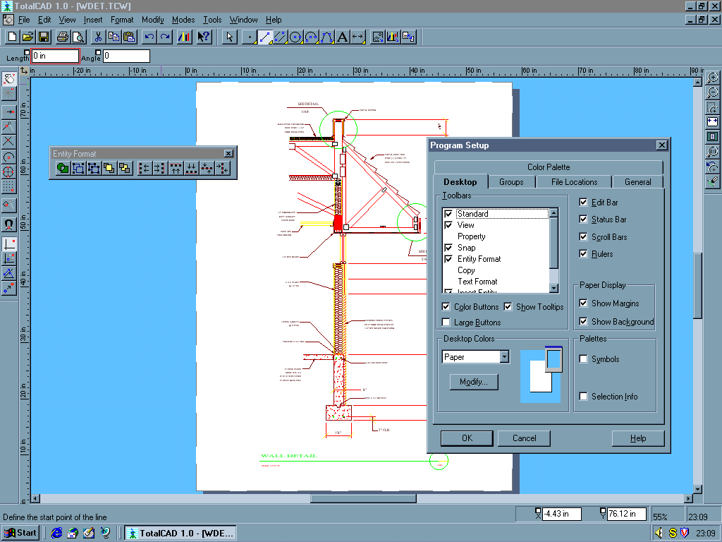
TotalCAD’s user interface is almost identical to that of TurboCAD, with toolbars for filing and entity drawing along the top, and Snap & Zoom toolbars at the sides. There’s also an Edit Bar above the main window and a right-button mouse menu, both of which change to suit the task in hand. TotalCAD depends on themed toolbars – as well as the defaults there are others for tasks such as entity modification and text formatting. They’re accessible from the View/Toolbars dialogue.
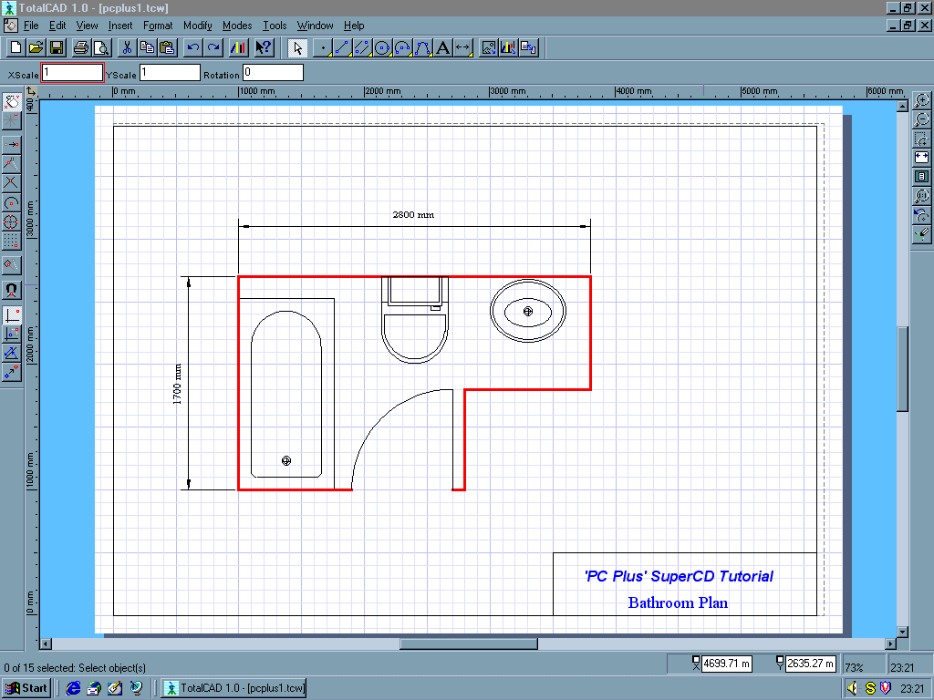
As an introduction to some of TotalCAD’s features, we’ll draw a simple plan of a domestic bathroom. Using the supplied templates and wizards greatly eases the job of setting up the working environment, sorting out things like the relationship between the size of the object, the paper size and orientation, and the scale. Although it’s still a bit laborious, it pays dividends later in terms of understanding and controlling what you’re doing.
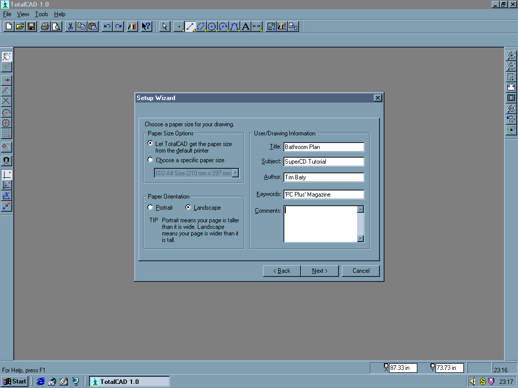
Go to the top toolbar and click on New drawing, which opens a dialogue box from where you can choose a suitable template or wizard –our exercise uses ‘Wzmetric’. The wizard’s first page deals with design units and numerical precision – check that the defaults are set for millimetres at 2 decimal places, and go to the next sheet. The second page covers drawing size and orientation, which should be set to Landscape. Fill in the drawing’s title and subject while you’re here. The final page of the wizard sets the drawing scale – choose 1:20 from the pop-down list.
You’ll now see a gridded drawing sheet, with a dashed line showing the useable area. TotalCAD’s default settings sometimes cause a mismatch between your printer settings and TotalCAD’s sheet size – this can usually be cured by going to the File/Page Setup dialogue and changing the Printer paper settings to A4 landscape.
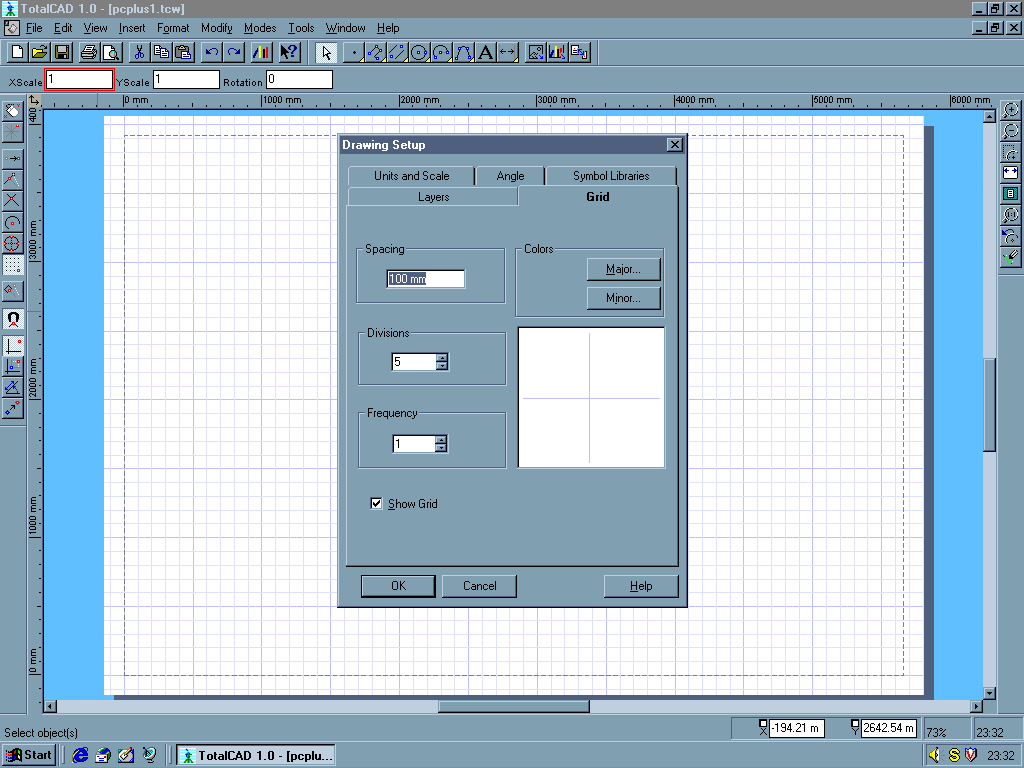
We’ll set up the working environment by switching on Grid from the Snaps toolbar and right-clicking the button, which brings up the Drawing Setup dialogue. Check that the grid increment is 100mm – you can also use this dialogue-box to change your drawing units or scale factor. Finally, switch on Magnetic Point, to make points visibly jump to the nearest grid or snap-point.
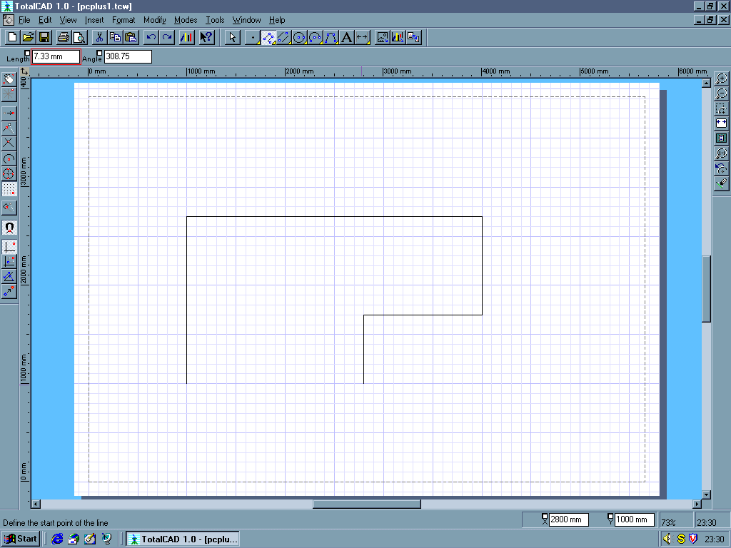
To draw the bathroom walls, select Multiline from the top toolbar. If you can’t see Multiline, hold the left mouse button down over the Line icon and an icon-strip will pop down. Place the first vertex somewhere in the lower left of your drawing– you’ll now see a ‘rubber-band’ joining your vertex and the cursor. It’s often useful to force lines to be exactly horizontal or vertical, which you can do by holding the Shift key down as you drag the cursor. If your room is an awkward shape, you can key exact dimensions using the Edit bar – press the ‘Tab’ key to highlight an Edit bar box, and enter the figure you want. Press ‘Enter’ to return to mouse control. Continue to place the other points, and finish by double-clicking the first point. If you make a mistake you can use TotalCAD’s multi-level Undo and Redo to sort out the mess.
Inevitably, you’ll need to make adjustments once you’ve drawn a few objects. In our example we’ll centralise the room outline in the sheet – while we’re about it we’ll thicken the rather weedy-looking lines to make the walls a bit more obvious. Click on the Select arrow on the top toolbar to start Edit mode, and click the outline of the room. You’ll see a selection-box enclosing your room boundary, with several different editing handles. Ignore the ones around the edge, and point at the yellow blob in the centre – the cursor changes to crossed arrows. Click here and drag the boundary to the middle of the sheet. As long as you drag with the yellow handle TotalCAD will use grid & snap settings or keyed dimensions to position objects accurately. You can move the yellow handle within the selection by holding down the Control key and clicking. While the room boundary is still highlit, right-click on it to bring up the mouse menu and choose Properties. Click the Pen tab and choose a line-width of 1mm.
At this point it’s helpful to create some drawing layers. Layers control the visibility of similar objects, and are fundamental to managing the information in your drawing. Bring up the Layers dialogue from the Tools/Layer menu – you’ll see default layers for hatches, dimensions and so on. Key in ‘Walls’ in the empty text-entry box. Click the New button, and you’ll see your layer added to the list. Highlight your new layer and change its colour to red using the list-box. Add another layer called ‘Fittings’, and set its colour to blue using the same technique. Bring up the boundary’s Properties box again and change its layer to Walls – you should also change its colour to ‘By Layer’. When you close the dialogue your walls should turn red.
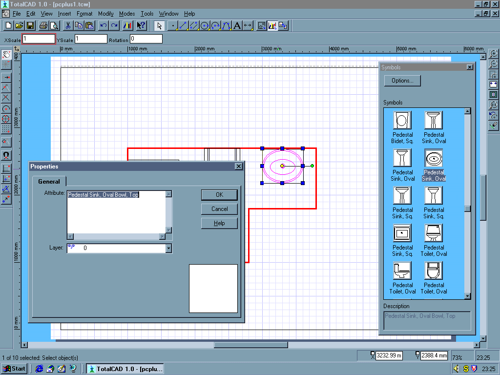
TotalCAD installs an extensive library of symbols to help with common tasks. We’ll need to link the Bathrooms library to our drawing. Open the Symbol Libraries dialogue from the Tools/Symbol Library menu, and click ‘Add’. You’ll see a file dialogue-box – navigate to the TotalCAD\Symbols\Bath folder, highlight it and close the dialogue box. You’ll now see ‘Bath’ in the list of libraries. To use the symbols, open the Symbols palette from the View/Symbol Library menu. Scroll though the palette’s icons until you find ‘Bathtub, Standard’ – there are several varieties, so look at the text panel to decide which one you want. Click on a bath’s palette icon and drag it into your drawing –the symbol loads, and you can then use the handles or Edit Bar to reposition it. Use the green handle if you need to rotate the symbol, and place the toilet and basin using the same techniques. If you need to create your own symbol, you can use any TotalCAD drawing, as well as AutoCAD DXF files.
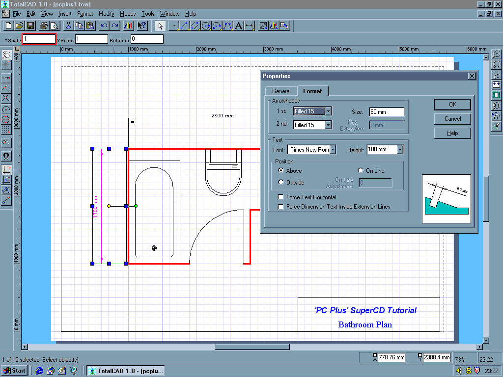
To make our design look a little more professional, we’ll add a simple drawing border and some dimensions. Use the Rectangle icon on the top toolbar to put a frame just inside the dashed lines around the edge of your sheet, and add a couple of lines for a title-block. Next, we’ll add some text for the title. Click on the Text icon, and then right-click it to bring up the Text dialogue-box. Go to the Text tab and choose the font, style and colour you want. Click on a point or the text’s origin, and key in the title. If you don’t like the result you can easily change the text’s appearance by highlighting it and bringing up its Properties dialogue.
Finally, we’ll add some dimensions. Click on the Horizontal dimension icon, and make sure that Vertex snap-mode is switched on. Place the first leader origin on the top left-hand corner of your room boundary, followed by the second leader on the top right. Set the dimension-line position a few grid squares above the top room boundary-line. Repeat the process with a vertical dimension down the left-hand side and you’re finished.
Although we’ve only scratched the surface in this tutorial, it’s hopefully clear that TotalCAD is a highly capable and easy-to-use 2D draughting program. If you like it, we’d encourage you to practise with Snaps, the Edit Bar and Symbol Library features to get the most out of the program. All these and more are in the on-line tutorials and Acrobat manual, so try out the exercises described there. If you get on well with TotalCAD, you can upgrade easily to either TotalCAD 2D/3D or TurboCAD. Happy draughting!
Tim Baty