| Publication Details: | |
|---|---|
| Publication: | “PC Plus”, UK |
| Issue: | |
| Date: |
Getting Started: SoftCAD.3D Lite V1.16
SoftCAD.3D Lite V1.16 is a Product Visualisation program, with a bias towards architectural work. It includes features such as stairs and terrain modelling, and a library of building-related objects. If you like it there’s an upgrade path to the full version of SoftCAD.3D or ArchiTECH.PC, a dedicated architectural design program.
When you start SoftCAD.3D you’ll see a 3D workspace, with toolboxes along the left and bottom. The lower toolboxes contain things you’ll need constantly, like drawing-plane and viewpoint controls, and co-ordinate entry-boxes. The side toolboxes are arranged hierarchically in three levels. The Main toolbox accesses the primary function-groups –it brings up one of six secondary toolboxes, dealing with object selection and editing, terrain modelling, drawing, symbol libraries, solid editing, and rendering & animation. Selecting a command presents you with a context-sensitive Parameters Palette.
SoftCAD.3D makes extensive use of the right-hand mouse button for terminating commands and accessing options. The left button selects icons and places points in the normal manner. If you prefer, there’s an extensive set of keyboard shortcuts. As always, it’s worth thoroughly exploring the on-line help, cursor tooltips and status-line help text to work out what’s where. If you want to delve deeper, the SuperCD includes some ScreenCams and Acrobat-format Training Exercises.
For out tutorial we’ll indulge in some architectural history and model a simple classical Greek temple. There are three main modelling stages –the columns, the beam (the Architrave), and the gable-end (or Pediment). Finally we’ll set up the viewpoint and render the finished article. You’ll find our walkthrough screenshots on the SuperCD.
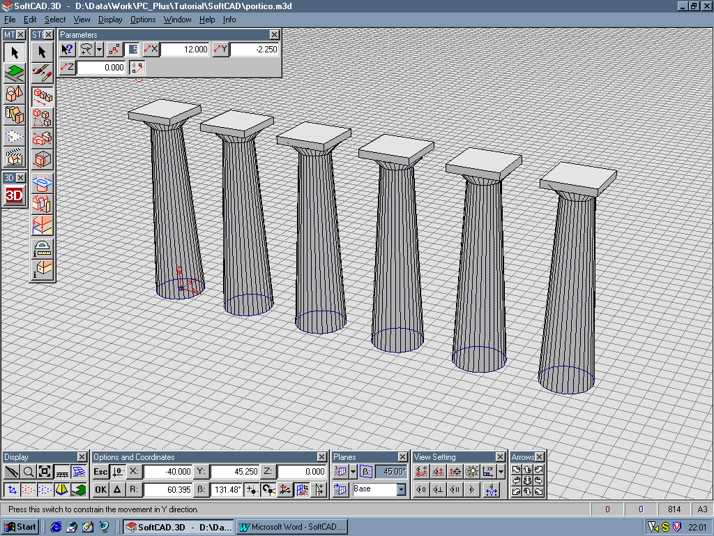
To draw a column, select the Column tool from the Object secondary toolbox and set the number of faces to 32 in the Palette. Place the central axis, and set the radius with a left click. Right-click in the same position to start defining the height – if you left-click you’ll be prompted to turn your circle into a pie-slice. Left-click to set the height, and again to set the angle of the sides. The sequence then starts again for the next section.
Our column requires three sections – the shaft, the capital (or Echinus) and the top-plate (the Abacus) – check the screenshots for the required shape. When you start the Abacus, change the number of polygon faces from 32 to 4. Right-click to finish the whole thing. If you make a mistake, the backspace key will undo each stage. If you can’t see everything, zoom out by right-clicking the centre icon in the Arrows toolbox.
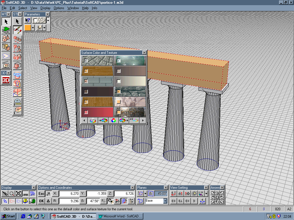
Next we’ll modify the column’s surface texture. Pick the Arrow tool on the Select secondary toolbox, and click Select by Polygon/Lasso from the Open Selection Alternatives Palette. Draw lasso lines around the column, and right-click to finish selecting it. To change its texture, open the Surface Color and Texture palette, choose the surface you want (we used Granular) and pick the Change Surface of Selection button.
We’ll use the Move command on the Select secondary toolbox to copy the column. Before you place any points change the Number of Copies in the palette to 5. Now switch the 2D/3D Positioning icon to 2D mode, and set a point near the column base. As you move the cursor around it’ll change shape when it’s near a vertex, an edge and so on – when you pick a point the cursor snaps precisely to that feature. Place the next column a suitable distance away, using the ghost images for guidance.
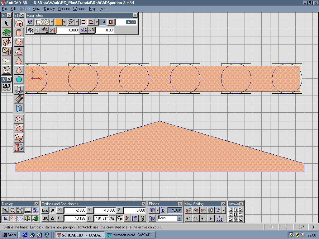
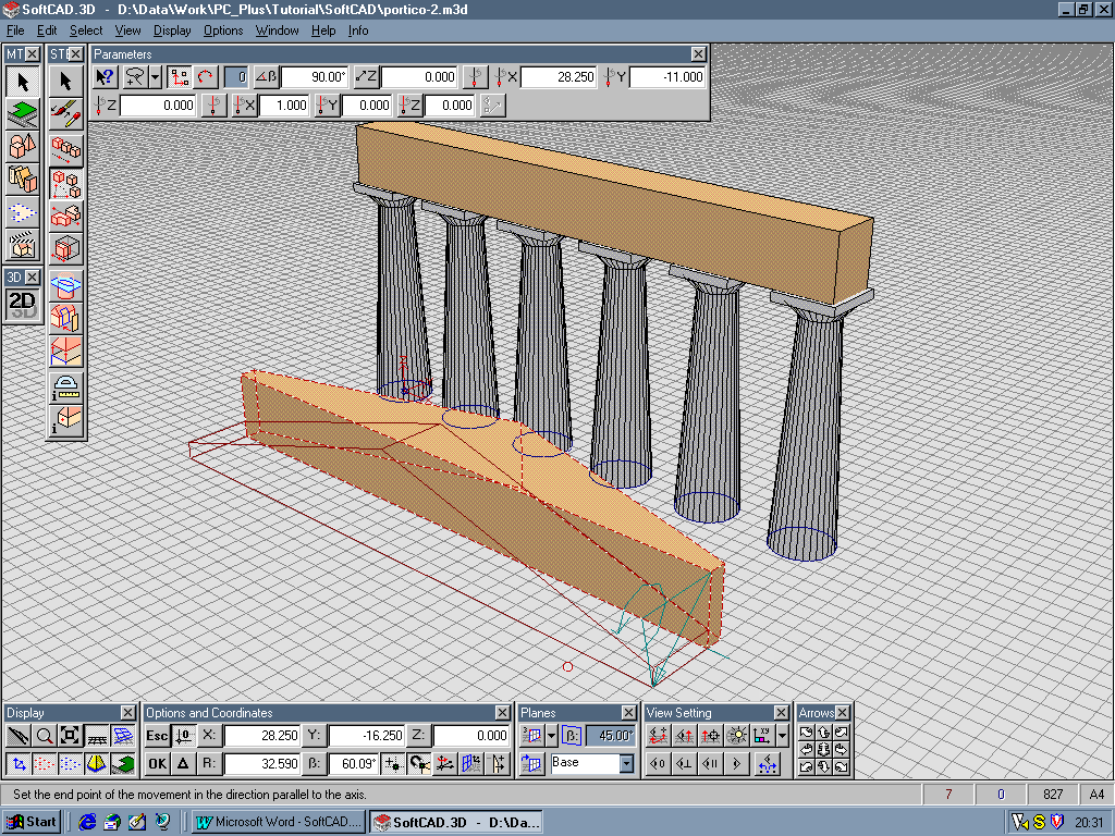
It’s a simple task to create the Architrave using the Box tool on the Object toolbox. Make it slightly smaller than the columns’ tops, and use a contrasting surface – in our example we used Granite. For the Pediment, model a shallow triangular prism on the base plane and use Rotate on the Select toolbox to orientate it correctly. Make sure the axis’ rotation arrow points the right way, and key the required angle in the palette. The Pediment will rotate, at which stage you can move it on top of the Architrave.
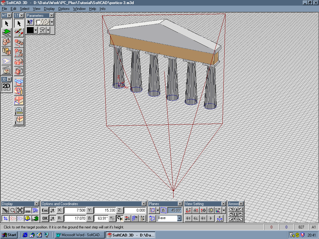
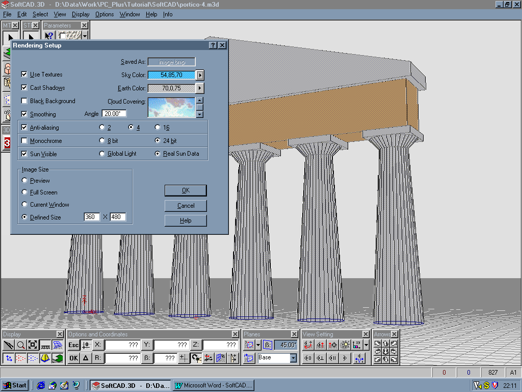
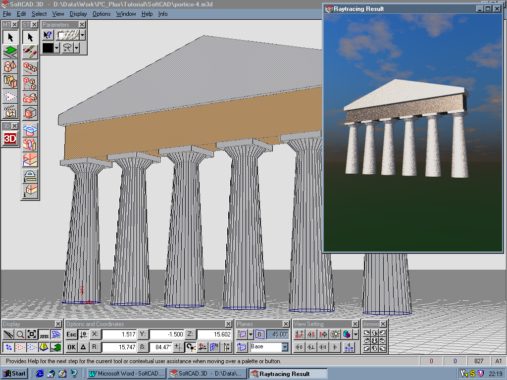
All that remains is to set up a viewpoint with the View Setting toolbox. Use the Arrow toolbox centre icon to zoom out from the model, and use the Panorama View icon on the View Settings toolbox to set the view and target positions. Finally, we’ll set up the rendering options from the Display menu – it’s a good idea to switch on Smoothing and Anti-Aliasing, both of which greatly improve the end results. Start the rendering calculation, and you’ll see a progressively higher-resolution image build in the preview window. If it’s incorrect just close the window and change your settings.
Although we’ve only scratched the surface here, there are plenty of other features worth investigating, from the symbol library to lighting controls for the renderer. While it’s not as sophisticated as 3D Studio, SoftCAD.3D Lite is considerably easier to learn.
Tim Baty
Walkthrough: Creating a model in SoftCAD.3D Lite V1.16