| Publication Details: | |
|---|---|
| Publication: | “PC Plus”, UK |
| Issue: | 138 |
| Date: | April 1998 |
SuperCD Tutorials: bCAD 2.2
bCAD 2.2 for DOS is a freeware 3D modelling and rendering package from the ProPro Group Inc., of Novosibirk, Russia. Despite its public-domain origins, it’s a surprisingly capable program – as well the surface modeller and photo-realistic renderer there’s a set of 2D draughting tools, making it a versatile all-rounder. Naturally, ProPro hope that bCAD for DOS will encourage users to investigate their commercial offering, bCAD 3 for Windows 95, which competes with established modellers like Autodesk’s 3D Studio.
When bCAD first starts you’ll see the main icon toolbox and an empty editor window. The toolbox contains icons for loading designs, printer setup, configuration, and functions such as viewing bitmaps and editing fonts. The editor window has an icon toolbar on the left – each icon brings up another icon toolbox or dialogue-box. At the bottom of the window there’s a command-prompt – it’s important to check this constantly, to see what the program wants you to do next.
Although bCAD runs in MS-DOS, its keystrokes and window controls are similar to Microsoft Windows 3.1 and UNIX X-Windows. There are buttons to maximise, minimise and close windows, and you can re-size and move windows using the frame and banner. The working environment feels nicely intuitive, and the ‘home-made’ windows interface is certainly no hindrance.
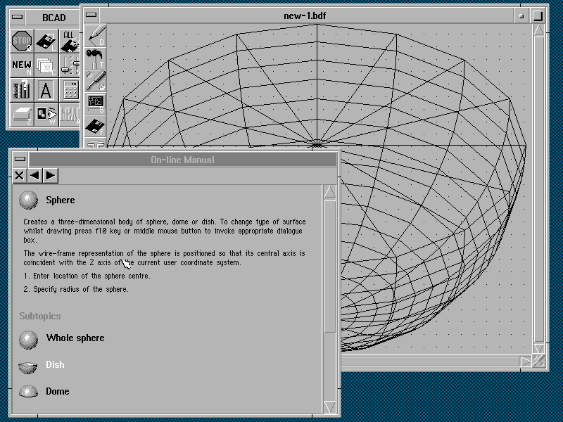
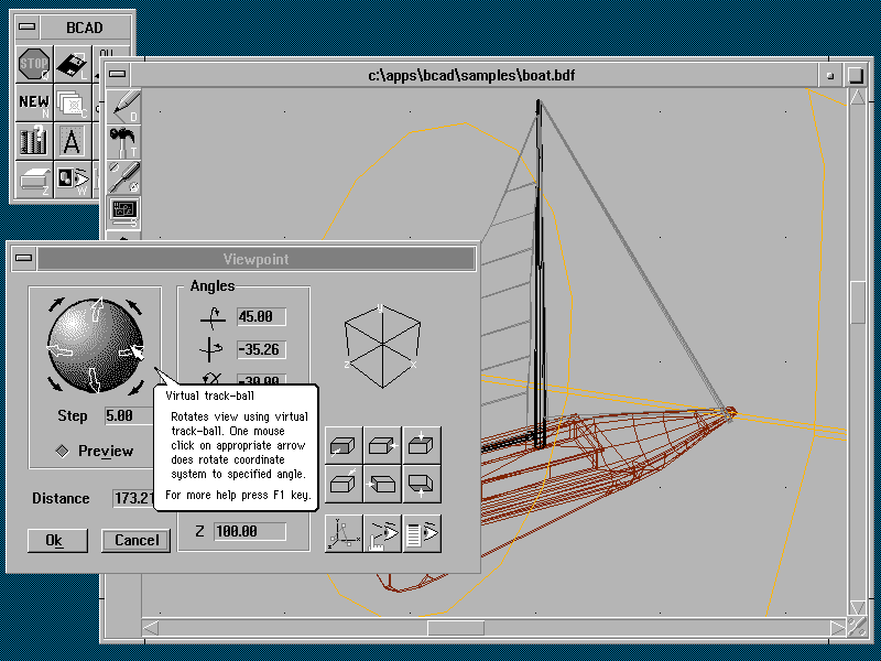
The F1 key opens an on-line reference manual – it’s context sensitive, so if you point at something and press F1 you’ll get the relevant page. bCAD also uses cursor tooltips, which you can optionally make more verbose. The tooltips make a real difference while you’re learning the program, and it’s worth spending time just browsing around the interface to see what each feature does.
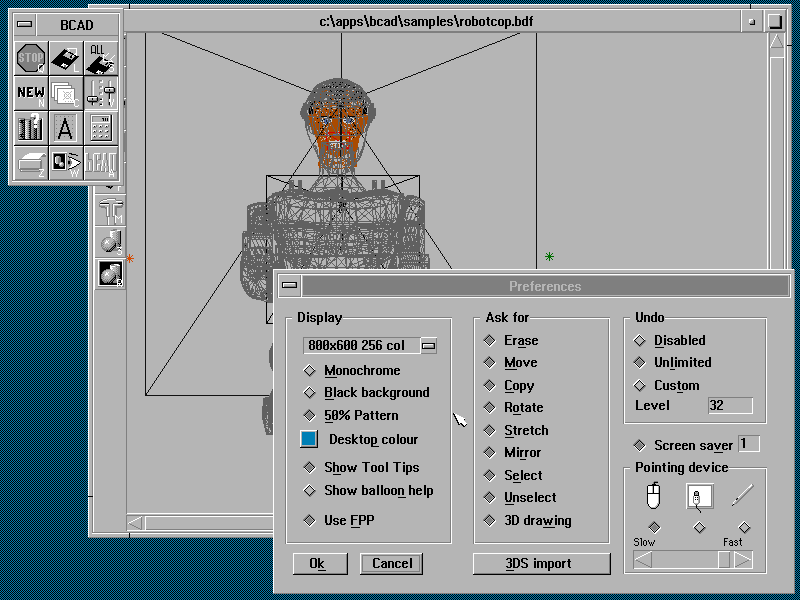
Once you’ve worked out where everything is, it’s sensible to refine the working environment to suit your tastes. Click on the Preferences icon in the main toolbox, and you’ll see a dialogue-box for the display, mouse, tooltips and undo command. The default video-mode is standard VGA (640×480, 16 colours), which restricts some rendering features – we’d recommend at least 256 colours if possible. To change video, click the list-button next to the description, and double-click the mode you want – if the test-pattern that follows looks scrambled, you’ve probably chosen a mode that your video-card or monitor don’t support. When the normal screen returns, just choose a simpler mode and try again.
The only sign of bCAD’s DOS underpinnings is the extensive use it makes of the keyboard – there’s a keyboard short-cut for every icon, and the function keys activate different dialogue-boxes. The F9 key, for instance, opens a Windows-style scientific calculator. Most drawing commands have additional options accessible through the F10 key, which brings up a context-sensitive toolbox.
When you use a CAD system, whether it’s a simple 2D program or a 3D modeller like bCAD, it’s essential to understand how to position features accurately in your design – placing points ‘by eye’ is seldom precise enough. bCAD gives you grid, coordinate and object-snap methods. With grid point-placement, the cursor jumps to the nearest position in an invisible grid – pressing the F7 key brings up bCAD’s Grid dialogue-box, where you can change the step-size or switch it off altogether. If you need to place something to a known dimension you can key in an x, y, z coordinate value – a dialogue-box appears as you start typing. You can also specify distances relative to the previous point by prefixing coordinates with the ‘@’ symbol. Another dialogue-box is available via the F6 key, which controls Cartesian or polar coordinate display, units, and the working plane’s position. Finally, object snap allows you to fix points to geometrical features such as line ends or the centres of circles – the F8 key opens a dialogue-box where you choose the feature you want.
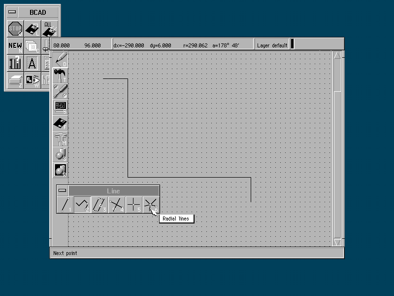
When you’re working within bCAD, you control almost everything from the icon toolbar in the editor window. The simplest topic to start with is the Drawing toolbox, at the top of the toolbar. This contains a reasonable collection of 2D objects, including lines, arcs, circles, text, and hatched areas. To get a flavour of how to draw, click on the Line icon and click again in the main window to place the first line-end. You’ll see a ‘rubber-band’ image of the line follow the mouse pointer around the screen. You can now either place the other end, or press the F10 function-key to bring up the Line toolbox – this allows you to select sequential lines, parallel lines and so on. Follow the command-prompt at the bottom of the screen until the operation finishes – the command will then auto-repeat, and you can either draw some more or stop with the right mouse-button or ‘Esc’ key.
All the other drawing commands operate in a very similar manner. In almost every case you place the first point, then either select another mode from the F10 toolbox or continue fixing points. While you’re drawing or editing an object, you’ll see a coordinate display along the top of the editor window showing the absolute cursor position and the relative distance from the last point. A dialogue-box appears automatically if the operation requires more information.
As your design progresses, you’ll need to erase mistakes or modify your work. The Transform toolbox contains icons for basic editing tasks such as Erase, Move, Copy, Mirror, Rotate and Stretch. The toolbox also includes icons to help you select the objects you wish to manipulate. bCAD allows you to either choose a command first and then pick the object you want to edit, or select the objects you want and then choose what to do with them. As with drawing, you start the command and follow the instructions on the prompt-line. You can place any point accurately using the same keyboard coordinates or object-snaps as for drawing.
The Transform toolbox also includes an icon for editing polylines – you can move, add and delete vertices, curve the line, chamfer or fillet corners and so on. It’s important to understand polylines, as they’re used extensively to define edges or profiles for bCAD’s 3D surfaces.
The remaining icons in the Transform toolbox allow you to group and ungroup objects. As your design becomes more complex, you’ll often need to perform several operations on the same set of objects – for example, the objects which represent a desk in a room layout.
The Amend toolbox allows you to change object-specific settings for hatched areas, text, and the cameras and lights you’ll use in 3D rendering. You can also change properties such as colour, linetype and layer for any object. The colour dialogue-box includes controls for 3D surface-properties in the renderer. You can alter shininess and graininess, and the pattern on each surface – you can even apply bitmap images to surfaces.
Layers are an important method of structuring and controlling your design data – the trick is to create separate layers which represent different features, such as walls or furniture, and use the Change Layer icon to move an object onto the relevant layer. You can then switch layers off to temporarily hide the details you don’t need while you work on the objects you can still see.
Another important icon in the Amend toolbox is Undo – this allows you to step back through your work if you’ve done something wrong. If you really need to, you can step back all the way to the beginning of your bCAD session. You can change global undo settings on the main-menu Preferences dialogue-box.
If you want to change settings for new objects instead of those you’ve already drawn, you can find the icons you need in the Viewport Settings toolbox. All the dialogue-boxes activated by the function keys are here – drawing-modes such as colour, linetype and layers, and general setup functions for grid, snaps-modes and coordinates.
The Viewport Settings toolbox also contains icons to zoom in and out on details, and open extra editor windows onto your drawing. It’s here that you set up the viewpoint and working plane for 3D modelling – as you change the plane’s orientation, the viewpoint onto the model also changes so that the working plane is always aligned with your computer’s screen.
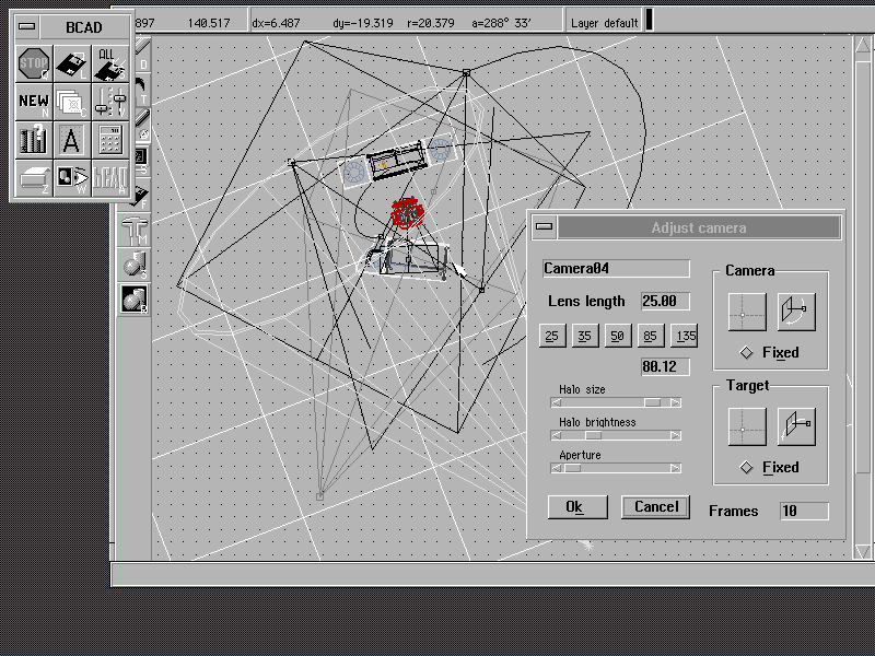
The last section of the Viewport Settings toolbox allows you to place camera and light objects in your design, which are used by the renderer. The camera can be static, or you can link it to 2D objects which define motion-paths for the camera and where it’s pointing. You can illuminate your design with spotlights, which are directional, or omni-directional lights which behave like a naked light-bulb. Each light has controls for the character and colour of the light.
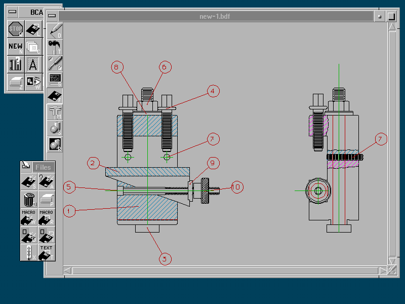
When you want to save or print your work, you must use the Files toolbox. bCAD supports a reasonable selection of printers, including HP Deskjets and Laserjets, Epson dot-matrix and several large-format plotters. The Files toolbox contains icons for reading or writing sections of your design – this would allow you to build a library of standard parts, for instance. It’s also possible to import and export AutoCAD DXF or 3D Studio files, and export several popular bitmap formats.
Although bCAD concentrates on 3D modelling and rendering, its 2D capabilities are significantly enhanced by a decent selection of dimensioning tools. Linear, radial and angular dimensions are all present, along with a variety of leader-lines. You can fine-tune the appearance of your dimensions, changing the size and format of arrow-heads and text – you can also add tolerance values to the dimension text.
The 3D Modeller toolbox is where you create objects in 3D. bCAD is a surface modeller – the 3D objects you draw are all thin meshes, with no awareness of what’s solid and what’s fresh air. Although this makes certain features awkward to draw (for instance circular holes in rectangular sheets), it’s easy to make the transition from 2D to 3D. Anything in 2D can be ‘extruded’ to give it height, and polylines can have each vertex set at different heights above the working plane. The 3D Modeller toolbox contains icons for 3D surfaces which are defined by 2D objects, including pyramids, surfaces of revolution, extrusions, ruled surfaces and tracked surfaces. In all these cases, you must draw something in 2D first, which you then select for the 3D operation. Ruled surfaces are typical – start out by drawing two lines approximately parallel to each other, then pick the Ruled Surface icon. Select the lines when prompted, and you’ll see a dialogue-box where you can control the density of the mesh – the larger the numbers, the finer the mesh but the slower the drawing. Although other mesh objects are useful, ruled surfaces are particularly powerful – you can select several 2D objects, and the ruled surface uses them to create complex 3D spline-curved surfaces. The 3D Modeller toolbox also contains pre-defined 3D objects such as boxes, spheres and cones.
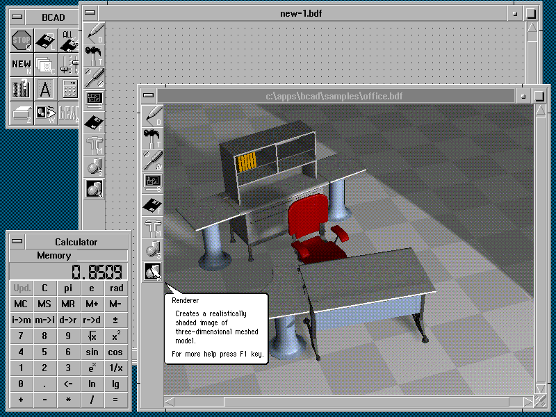
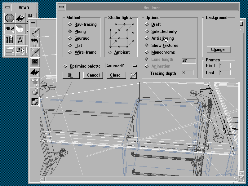
When you’ve completed your design, you can create a realistic representation of it in the Renderer. You can set up lights, import bitmap images for the background, and select the rendering method, from a simple wire-frame to a full ray-traced photo-realistic image. Although ray-tracing usually gives the most realistic results, it’s time-consuming. Phong shading is a more acceptable compromise between realism and speed – it includes surface patterns and textures and some advanced lighting controls, without the heavy processor demands imposed by calculating shadow-patterns. If your camera set-up includes motion-paths, bCAD will build a sequence of rendered images and compile them into an Animator FLC file. When you’ve finished, you can view your animation in the Bitmap Viewer window on the main toolbox.
Overall, we found it hard not to like bCAD. OK, it’s not the very latest technology and DOS programs are unfashionable, but it doesn’t demand exotic hardware or grab vast amounts of your hard disk, and is robust even when running under Windows. Above all, it’s easy to use and gives good results where it counts.
Tim Baty
| bCAD Function Keys | |
|---|---|
| F1 | Help |
| F2 | Colours & Materials |
| F3 | Linetypes |
| F4 | Layers |
| F5 | Drawing Aids |
| F6 | F6 |
| F7 | Grid |
| F8 | Snap Modes |
| F9 | Calculator |
| F10 | Context-sensitive toolbox |
| F11 | Zoom |
| F12 | 3D Viewpoint |